CSSE4011: Connectivity - GPIO
1.0 Motivation
The following tutorial explores exposing the board GPIO (General Purpose Input/Output) to userspace (an app) within Zephyr. Zephyr does things a little differently when it comes to interacting with hardware. In this tutorial, we will use the GPIO API to interact with GPIO pins.
1.1 Test Hardware
-
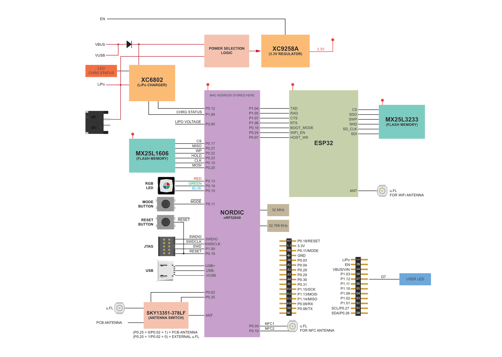
Particle Argon
-
2 x mUSB Cable
-
Segger J-Link EDU mini
This implementation is valid for Zephyr RTOS Version 3.0.XX
1.2. Prerequisites
Ensure that you have completed/understand the following tutorials.
- OS.1, OS.2, OS.2.1 and BRD.1
1.3 Setup
Connect the Arduino sense board to the host machine and ensure that the development environment has access to the device (USB passthrough to virtual machine).
2.0 Zephyr GPIO Implementation
2.1 Boilerplate
The following commands assume that you have setup your files/directories following the respective tutorial(s).
Create a new application directory for a sample gpio application.
For setting up a basic boilerplate for our application, we will use the provided blinky sample in Zephyr.cd ~/csse4011/zephyrproject/zephyr/samples/basic/blinky
cp -R * ~/csse4011/csse4011_repo/apps/gpio_sample/
cd ~/csse4011/csse4011_repo/apps/gpio_sample/
2.2 DeviceTree Summary
"A devicetree is a hierarchical data structure that describes hardware...Zephyr uses devicetree to describe the hardware available on its Supported Boards, as well as that hardware’s initial configuration."
An extensive guide to DeviceTree Source (DTS) implementation can be found here & here. Later in this course, you might need to describe hardware in a DTS overlay file and add it to the build system for Zephyr to access particular hardware that you may need to use. Adding DTS overlays has been covered in OS.2.1-Building_Tips.
When an application is built for a particular board, Zephyr creates a final zephyr.dts file in the build directory. This file concatenates all selected hardware into this "final devicetree". Typically, it's a good idea to start here to see what the hardware description looks like for the current configuration of your build.
For instance, lets try building this boilerplate blinky app for the Particle_Argon.
Particle_Argon. This information is exposed to userland/application in Zephyr, using a set of macros see here.
In this tutorial, we are interested in GPIO, so we will look at how to toggle a particular GPIO pin from looking at the zephyr.dts file.
2.2 GPIO Interaction
Typically, when you interact with new hardware, you must first enable the kernel driver for it, this is usually done using a kernel configuration file (KConfig). In our case for GPIO, it is enabled in the prj.conf file in the application directory with CONFIG_GPIO=y. Most boards will typically have basic hardware functionality like gpio, uart and i2c enabled by default in the board definitions (in the Zephyr source). You can refer to OS.2.1-Building_Tips for a guide on adding segmented KConf files to the build system.
If you have already read through the blinky sample that we use as boilerplate, you may have already noticed that to toggle the led, it uses the device-tree macros from within the main.c file.
For example,
/* The devicetree node identifier for the "led0" alias. */
#define LED0_NODE DT_ALIAS(led0)

#if DT_NODE_HAS_STATUS(LED0_NODE, okay)
#define LED0    DT_GPIO_LABEL(LED0_NODE, gpios)
#define PIN     DT_GPIO_PIN(LED0_NODE, gpios)
#define FLAGS   DT_GPIO_FLAGS(LED0_NODE, gpios)
DT_ALIAS() is used to find the reference led0 within the DTS. This is a special case of using an alias. If we look in the zephyr.dts file, you will notice that led0 is specified as aliases{}. So this macro "returns a node identifier for the node which is aliased".
When you follow the led0 alias in zephyr.dts, you will notice that it simply maps to a GPIO pin. Aliases can help abstract the hardware within the devicetree and make them easy to access.
2.4 DeviceTree GPIO Access
Lets investigate toggling a particular GPIO without using it's alias. Why not just make an alias for it? So we can learn how to use DT-Macros in Zephyr.
We will use the Particle Argon for this tute. You can find the board pinout here. We will use the GPIO pin P0.13 (internally connected to the RGB-red led). This pin maps on P0 (port 0), in the zephyr.dts this is gpio0. For instance, pin D6 (p1.11), will be in gpio1.
Start by editing the source file and append the following
UseDT_NODELABEL to get the respective node_id for for gpio0 from DTS.
/* DeviceTree get node ID from label */
#define GPIO0 DT_NODELABEL(gpio0)
#define GPIO0_13 0x0D                //PIN PO.13
const struct device *dev_gpio0;
dev_gpio0 = device_get_binding(DT_LABEL(GPIO0));

/* Configure PIN_A0 as an Output with that is Active Low */
ret = gpio_pin_configure(dev_gpio0, GPIO0_13, GPIO_OUTPUT_ACTIVE | GPIO_ACTIVE_LOW);
device_get_binding() will not except a NODE_ID, but it does accept a NODE_LABEL, hence why DT_LABEL is used. DT_LABEL is a helper macro that does the same as DT_PROP(GPIO0, label). The struct device see here returned by this function call describes the particular hardware and is used by the API to interface to that particular device/hardware.
and finally in our while loop, we can toggle this pin.
while (1) {
    gpio_pin_set(dev, PIN, (int)led_is_on);
    /* Toggle the PIN */
    gpio_pin_set(dev_gpio0, GPIO0_13, (int)led_is_on);
    led_is_on = !led_is_on;
    k_msleep(SLEEP_TIME_MS);
}
4.0 Testing
This application can now be built and flashed using:
You should see that the red led is now flashing as well as the blue led (led0) from the boilerplate code (if you didn't remove that code).
4.1 Sample Application
A sample application has been provided, this application includes all the steps mentioned above.
Sample is located in:
- REPO_TOP/tute_solutions/gpio_sample/